I've written a number of blog posts about wireless communications, primarily 315/433Mhz ASK/OOK modules and 2.4Ghz GFSK modules. In this article I'll analyze the pros and cons of each.
![]()
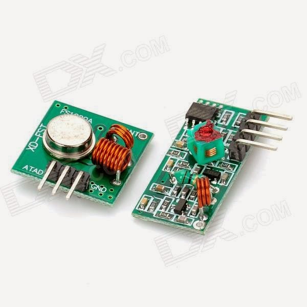
UHF ASK/OOK modules
ASK modules are the simplest type of communication modules, both in their interface and in their radio coding. Single-pin operation allows them to be used with a single GPIO pin, or even with a UART. The 315 and 433Mhz bands can be received by inexpensive RTL-SDR dongles, making antenna testing relatively easy. At 78c for a pair of modules, they are a very inexpensive option for wireless communications for embedded systems. The bands are popular for low-bandwidth keyless entry systems, so fob transmitters are widely available for 315 and 433 Mhz.
For a given power output budget, 315Mhz communications has the best range since free-space loss increases with frequency. Using 433Mhz means about 3dB more attenuation than 315, and 2.5Ghz has about 15dB more attenuation than 433. The 315 and 433Mhz bands can be used for low-power control and intermittent data in the US and Canada, but in the UK it looks like only the 433Mhz band is available. Due to the simple radio encoding involving the presence or absence of a carrier frequency, sensitivity is over 100dB. Superheterodyne receivers have a sensitivity in the -107 to -111 dB range, while super-regenerative receivers have a sensitivity in the -103 to -106 dB range.
The inexpensive super-regenerative receivers may need tuning, though this can be avoided by using the more expensive superheterodyne receivers which use a crystal for a frequency reference. High-level protocol requirements such CRC or addressing must be handled in software, although libraries such as VirtualWire can greatly simplify this task.
Although the specs on most transmitters indicate an input power requirement between 3.5 and 12V, the modules I have tested will work on lower voltages. I tested a 433Mhz transmitter module powered by 2xAA NiMH providing 2.6V. At that voltage, the transmit power was about 9dB lower than when it is powered at 5V.
As David Cook explains in his LoFi project, it is feasible to use CR2032 coin cells to power projects using these modules. Depending on the MCU power consumption and the frequency of data transmission, even 5 years of operation on a single coin cell is possible.
2.4Ghz modules
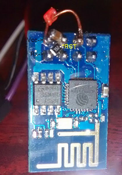
I've written a few blog posts before about 2.4Ghz modules, both Nordic's nRF24l01 and Semitek's SE8R01. The nRF chip has lower power consumption of 13.5mA in receive mode, than the Semitek module which consumes 19.5mA. Either module can still be powered from a CR2032 coin cell. When using a 50-100uF capacitor as recommended by TI, capacitor leakage can add to battery drain, so use a higher voltage capacitor, such as 16 or even 50V as these will have lower leakage.
Nordic's chip has lower power consumption, you might not get a real nRF chip when you purchase a module. Besides higher power consumption, some clones are not compatible with the genuine nRF this can range from completely unable to communicate with nRF modules like the SE8R01, or simply inability to work with the dynamic payload length feature. With SE8R01 modules selling for only 41c in small quantity, if you don't require compatibility with the genuine nRF protocol, and aren't planning to try bit-banging bluetooth low energy, then these seem to be the best choice. One other reason to go with genuine nRF modules (if you can find them for a reasonable price) is for range. At 250kbps, the nRF has a receiver sensitivity of -94 dBm. The SE8R01 doesn't have a 250kbps mode, and at both 500kbps and 1mbps the receiver sensitivity is -86 dBm.
Although the power consumption of 2.4Ghz modules is similar to UHF ASK/OOK modules, the higher data rate permits lower average power. Take for example an periodic transmission consisting of a total of 10 bytes: 1 sync, 3 address, 4 payload data, and 2 CRC bytes. At 250kbps the radio would be transmitting for only 320uS and needs to be powered another 130uS for tx settling time, making the total less than half a millisecond. An ASK/OOK module transmitting at 9600kbps would have the radio powered for a little over 8ms. For a periodic transmission every 10 seconds, and with sleep power consumption of 4uA, the ASK module would consume an average of 21uA, compared to just 5uA for the nRF module.
Although the power consumption of 2.4Ghz modules is similar to UHF ASK/OOK modules, the higher data rate permits lower average power. Take for example an periodic transmission consisting of a total of 10 bytes: 1 sync, 3 address, 4 payload data, and 2 CRC bytes. At 250kbps the radio would be transmitting for only 320uS and needs to be powered another 130uS for tx settling time, making the total less than half a millisecond. An ASK/OOK module transmitting at 9600kbps would have the radio powered for a little over 8ms. For a periodic transmission every 10 seconds, and with sleep power consumption of 4uA, the ASK module would consume an average of 21uA, compared to just 5uA for the nRF module.
Conclusion
For low-speed uni-directional data, a UHF ASK/OOK module will work fine, and is the simplest solution. For reliable bi-directional communication, or for high bandwidth 2.4Ghz modules are the best choice.